Time: 2 September 2023 |
Source: Acrel
Engineer: Besty Chen Tel: +86 18761509710 E-mail: besty.chen@email.acrel.cn
Jiangsu Acrel Electrical MFG Co. Ltd
Abstract: As one of the clean energy sources, the installed capacity of wind farms has grown rapidly in recent years. Wind farms are divided into onshore wind farms and offshore wind farms. Generally, they are located in remote locations, with scattered installations and harsh environments. Therefore, wind farms need a remote monitoring system to facilitate operation and maintenance personnel to manage wind farm operations more efficiently.
Keyword: wind farm, centralized monitoring system, box transformer measurement and control device
1.Electrical equipment for wind farms
The top cabin of each generating set is equipped with a turbine generator, and the front end is an adjustable fan blade. The system can adjust the inclination angle of the fan blade according to different wind conditions. The general speed of the fan blade is 10-15 rpm points, through the gearbox can be adjusted to a speed of 1500 rpm to drive the generator. An industrial PLC is also configured in the machine room for control and related data collection. The wind speed, wind direction, rotation speed, active power and reactive power of power generation and other related data are collected through the PLC, and the generator is controlled in real time through the collected data. On land, a box transformer is installed at the bottom of the wind tower to be responsible for boosting and converging. According to the power and geographical conditions, multiple wind turbines are boosted once and connected in parallel for converging to the boosting substation. Send electricity to the grid. The electrical wiring diagram of the wind farm is shown in Figure 1. The voltage emitted by the fan is generally 0.69kV, which is boosted to 10kV or 35kV by the box transformer. After multiple parallel confluences, they are connected to the low-voltage side busbar of the step-up substation, and then boosted to 110kV or higher by the main transformer. into power grid.
Different from onshore wind power, due to the harsh environment of offshore wind power (high humidity, high salt density), the dry-type transformer used for primary boosting is integrated in the engine compartment of the draught fan, which not only solves the problem of the entire unit’s footprint, but also it avoids the difficulty of protection caused by installing the transformer at a lower position.
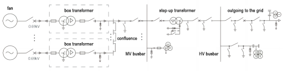
Figure 1 Schematic diagram of electrical wiring of wind farm
2. Protection and measurement and control equipment for wind farms
From wind turbine power generation - booster box transformer - confluence - booster station medium voltage busbar - main transformer - booster station high voltage busbar - high voltage outlet - grid connection, the middle needs to be boosted twice before being merged into the grid The power grid has a large number and types of electrical equipment, and any failure in any link will affect the normal operation of the wind farm. Therefore, it is necessary to set up protection and measurement and control devices in all links of the wind farm to comprehensively monitor the operating status of the wind farm. Figure 2 is a schematic diagram of the configuration of the protection and measurement and control devices of the wind farm.
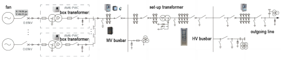
Figure 2 Configuration diagram of protection measurement and control devices for wind farms
2.1 Box transformer measurement and control device
In order to reduce line loss in onshore wind farms, a 0.69/35(10)kV box-type booster station is generally installed next to the wind turbine. The distance between the wind turbines in the wind farm is hundreds of meters, which is far away from the central control room. The step-up transformers are located in the open field, and the natural environment is relatively harsh, which makes manual inspection difficult. The measurement and control device of the box-type transformer is the core part of the monitoring system of the wind farm, which realizes intelligent management of the box-type transformer. The box-station measurement and control device can protect and remotely monitor the wind power box-station, fully realize the functions of "remote signaling, telemetry, remote control, and remote adjustment", and greatly improve the efficiency of wind farm operation and maintenance.
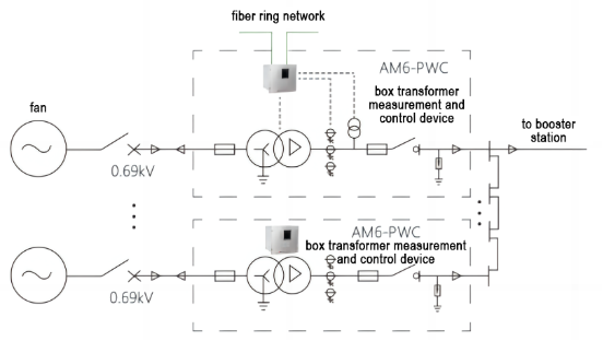
Figure 3 Wind farm box-station measurement and control device
The AM6-PWC box-type transformer protection measurement and control device is an integrated device integrating protection, measurement and control, and communication for different requirements of wind power and photovoltaic step-up transformers. Its functional configuration is shown in the table below.
Name | Main Function |
Remote metering | AC measurement: Three-phase current, three-phase voltage, frequency, power factor, active power, reactive power |
6 channels current, 6 channels voltage |
DC measurement: a total of 4 channels Standard 2 channels 4-20mA or 2 channel 5V DC Standard 2 channels thermal resistance (two-wire or three-wire system) |
Remote signaling | 29 channels of open input, of which the first 10 channels are fixed as non-power protection signal input |
Remote control | 6 channels relay outputs for protection output or normal remote control output |
Protection | Non-power protection: Light gas, heavy gas, high temperature, ultra high temperature, low transformer oil level, pressure relief valve conventional protection: three-stage current protection, zero-sequence current protection, overvoltage protection, low-voltage protection; zero-sequence overvoltage protection |
Communication | 2 self-healing optical fiber communication interfaces, which can form optical fiber ring network |
Ethernet communication interface 3 channels (optional, please specify when ordering) |
4 RS485 communication ports |
Protocol conversion | 4 channels configurable RS485 communication interface, free configuration and conversion of various protocols |
Record | Record the latest 35 accidents and 50 action records |
2.2 Low-voltage side line and busbar protection measurement and control
Multiple wind turbines are boosted to 35 (10) kV for the first time and then connected in parallel to form a circuit connected to the low-voltage side busbar of the step-up substation. . In order to achieve comprehensive monitoring, the line is equipped with line protection devices, multi-functional measurement and control instruments, power quality monitoring devices, and wireless temperature measurement devices to realize real-time monitoring of line electrical protection, measurement and temperature, and the low-voltage side busbars are equipped with arc protection devices.
| Item | Pic | Model | Function | Application |
line protection | 
| AM6-L | 35 (10) kV circuit current and voltage protection, non-electrical protection, measurement and automatic control functions. | line protection and measurement and control on the low-voltage side of the booster station |
power quality monitoring device | 
| APView500 | Real-time monitoring of power quality such as voltage deviation, frequency deviation, three-phase voltage unbalance, voltage fluctuation and flicker, harmonics, etc., record various power quality events, and locate disturbance sources. |
multifunction energy meter | 
| APM520 | It has full power measurement, harmonic distortion rate, voltage pass rate statistics, time-sharing electric energy statistics, switch input and output, analog input and output. |
bus arc protection |
| ARB6 | It is suitable for collecting the arc light signal and current signal of the switch cabinet, and controlling the opening of all switch cabinets on the incoming line, bus tie or bus | busbar protection on the low-voltage side of the booster station |
wireless temperature sensor | 
| ATE400 | Monitor the temperature of busbars and cable connection points of 35kV and below voltage distribution system and early warning of temperature rise. | temp. measurement of line contacts and bus bars on the low-voltage side of the booster station |
Table 1 Low-voltage side line, busbar protection measurement and control configuration
2.3 Main transformer protection measurement and control
After the wind turbine power generation is confluenced by the low-voltage side busbar, it is boosted to 110kV through the main transformer and connected to the grid. The main transformer is equipped with differential protection, high backup protection, low backup protection, non-electrical protection, measurement and control device, transformer temperature control, and gear transmitter to realize the protection, measurement and control function of the main transformer, and centralized group screen installation.
Item | Pic | Model | Function | Application |
differential protection device | 
| AM6-D2 | Differential protection on both sides of the main transformer | booster station main transformer |
high and low voltage side backup protection | AM6-TB | Three-stage phase-to-phase overcurrent, two-stage zero-sequence overcurrent, two-stage gap overcurrent protection, composite voltage blocking, two-stage zero-sequence overvoltage protection, circuit breaker control | booster station main transformer
|
non-electrical protection | AM6-FD | Heavy gas, light gas, over temperature, over temperature, pressure release protection and alarm | booster station main transformer
|
measurement and control device | AM6-K | Remote metering, remote signaling, remote control | booster station main transformer
|
temperature transmitter | ARTM-8L | Monitor main transformer winding and oil temperature | booster station main transformer
|
Table 2 Main transformer protection measurement and control configuration
2.4 High-voltage line protection measurement and control
The electric energy generated by the wind farm is boosted twice to 110kV and then incorporated into the power grid. The 110kV line is equipped with optical fiber differential protection, distance protection, anti-islanding protection, and measurement and control devices.
Item | Pic | Model | Function | Application |
protective device |
| AM6-LD | Line optical fiber differential protection device | both sides of the line |
AM6-L2 | Phase-to-phase/ground distance, zero-sequence overcurrent, fault location, etc. | this side
|
AM6-K | Remote metering, remote signaling, remote control |
AM5SE-IS | Anti-islanding protection device, when the external power grid is disconnected from the power grid |
power quality monitoring device |
| APView500 | Real-time monitoring of power quality such as voltage deviation, frequency deviation, three-phase voltage unbalance, voltage fluctuation and flicker, harmonics, etc., record various power quality events, and locate disturbance sources. | this side |
Table 3 110kV line protection measurement and control configuration
3.Wind farm monitoring system
The wind farm monitoring platform realizes the monitoring, control and management of the operating status of the wind farm and the real-time data of the wind turbines, improves the reliability and operation efficiency of the wind farm, reduces maintenance costs, and realizes intelligent management.
The wind farm covers a relatively large area, and the equipment is scattered. The system has relatively high requirements for data communication reliability and real-time performance. If conditions permit, the optical fiber redundant ring network can be used for data collection and communication, and the LORA wireless method can also be used for data transmission.
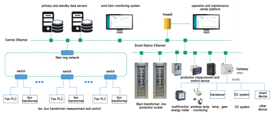
Figure 4 Wind farm monitoring system diagram
The data of the draught fan unit PLC and the box transformer measurement and control device are uploaded to the data server in the control room through the optical fiber ring network, and the data of the comprehensive automation system of the booster station are uploaded to the data server through the Ethernet. Transmitters, DC systems and other smart devices are connected to the communication management machine to upload data to the server.
3.1 Wind farm monitoring
Comprehensive display of the basic parameters of the entire wind farm draught fan (including wind speed, power, speed, etc.), and can realize the daily power generation, monthly power generation, annual The monitoring of power generation is convenient for real-time monitoring of the operating status of the draught fan.
3.2 Crew monitoring
Monitor the parameters and control status of each control module in the unit, including: pitch, yaw, gearbox, generator, hydraulic station, engine room, converter, power grid, safety chain, torque, main shaft, tower base, wind gauge, etc. Realize the comprehensive display of parameters, faults and trend graphs of each module.
3.3 Real-time data display
The draught fan, substations and other equipment in the wind farm are equipped with sensors and monitoring equipment, which can collect the operating electrical data, temperature, vibration and other parameters of the equipment in real time, and give timely warnings in case of abnormalities.
3.4 Power management
The display of active and reactive parameters, the control and adjustment of active and reactive power and other functions can effectively reduce the operating costs of enterprises and provide data support for the goal of energy conservation and emission reduction.
3.5 Production report
Display and report report functions for important parameters such as wind power, wind farm performance indicators, and unit new energy, and support statistics of the operation of each wind farm equipment according to the time dimension (day, month, and year). According to the query method of day, month and year, the important parameters are classified and counted by item, and the report is generated.
3.6 Statistical analysis
Support a variety of statistical analysis functions, fully tap the potential value of data, provide energy-saving optimization solutions, provide decision-making basis for managers, improve the management level of enterprises in a feasible way, and finally achieve the goal of energy-saving, emission reduction and scientific production. The analysis methods include: fault statistics, power curve, availability statistics, wind rose diagram, wind speed power report, monthly and daily utilization and downtime statistics, etc.
References:
[1] Acrel Enterprise Microgrid Design and Application Manual. Version 2022.05
Back To The List


.png)
.png) EN
EN